Project Description
Decarbonization : 17 tonnes of CO2 saved, based on an emission rate of 0.201 kgCO2/kWh consumed
Energy savings : 87 MWh per year
Your area : Haute-Marne (52) – region Grand Est
Sector : Metallurgy
Client’s needs – requests :
The feasibility study carried out for the foundry site concerns the energy optimization of the different areas of the company, namely
- The Savelli area
- The Epoxy Chain
- The paint line
Various solutions specific to each of these areas have been devised.
Project issues:
Analyze the available waste heat deposits, energy needs and equipment efficiency improvements specific to each of the study areas.
As a result of this characterization, Eco-Tech Ceram looked for the most appropriate solutions to meet the energy requirements and/or improve the energy efficiency of the workstations studied.
Each of the solutions was presented to the client via a complete report respecting the specifications of theADEME on feasibility studies.
Eco-Tech Ceram achievements:
Each waste heat recovery solution has been studied in such a way:
- Study of the principle diagram
- Sizing of equipment
- Thermal study of the solution
- Aeraulic study of the solution
- Solution design
- Energy and environmental balance
- Costing of the solution
- Economic study of the solution and financial arrangement
Each energy efficiency improvement solution has been studied in such a way:
- Study of equipment modifications
- Solution design
- Energy and environmental balance
- Costing of the solution
- Economic study of the solution and financial arrangement
Description of the proposed solutions:
The equipment that Eco-Tech Ceram has sought to recover waste heat from are the hydraulic power plant, the preheating tunnel and the firing tunnel.
The equipment on which heat can be recovered includes plate preheating, heating of the epoxy workstation, and heating of drying and preheating zones in the paint area.
Solution 1: Savelli zone
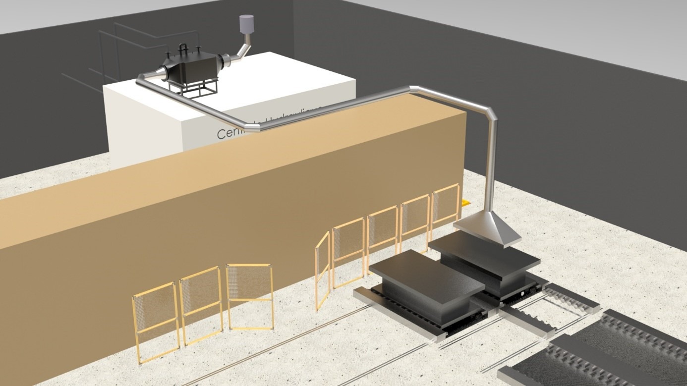
Visible below, it integrates a fatal heat recovery on the oil loop of the customer’s hydraulic power plant. This fluid transfers its heat to an oil/air exchanger with a capacity of 11 kW. An air flow is heated through the exchanger and allows the direct preheating of the customer’s products.
Visual:
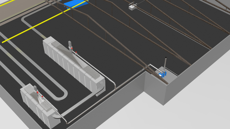
Solution 2: Epoxy chain
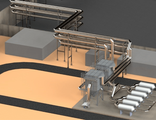
It concerns the recovery of waste heat from the baking and product preheating tunnels to the workstation in the Epoxy zone.
This valorization is made via a smoke/water exchanger. The fumes are sucked up by a fan common to both chimneys. The fumes give their calories to a water network and this water loop will feed different air heaters in order to homogenize the temperature at the workstation.
Visual:
Solution 3: The paint line
It consists in taking over the complete insulation around the painting line by placing insulating panels on the walls. This avoids significant heat loss at this station, even though it is an area intended for drying and preheating.

